14+ Furnace Diagram Wiring
Refer to unit wiring diagram section for wiring of sequencer for each model furnace. Repurposing the G wire for the C wire Single Stage Equipment Repurposing G wire for the C wire will result in the loss of continuous fan operation and air circulation features of the thermostat.
2
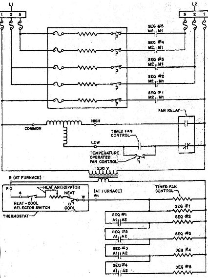
Connect the thermostat with Furnace 1 Furnace 2 and the DPST relays as shown in Figure 1 through Figure 3.

. Web Page 30 TABLE 3 Condenser Fan B4 Fan Motor B3 LRP14 Units Defrost Control Diagnostic LEDs LRP14 series units are equipped with a constant torque blower motor. C wire adapters are available here. Element rating labels and furnace wiring diagrams.
Connect the green wire to the G terminal. Start by familiarizing yourself with the various components in the wiring diagram. Lets look at the G wire.
Of the Y Y1 and Y2 wires Y or Y1 go to the Y terminal and Y2 to the Y2 terminal. If applicable drill guide holes before adding anchors to the wall. Web In this article we will break down the basic gas furnace wiring diagram and explain the various components and their functions.
Web 3 Run an additional wire from your equipment to the thermostat. Web Thermostats use 24 volts AC from a transformer to control a furnace. Table1 Kit Contents.
This wire goes to the G terminal on your new thermostat. Connect the red wire to the RC terminal. Web Page 1 G40UH X series units are midefficiency gas furnaces used for upflow or horizontal applications only manufac- tured with Lennox Duralok Plus heat exchangers.
Web If you have a C wire place it into the C terminal on your wall plate. At the heart of the gas furnace wiring diagram. Page 12 Remove tape to release blower access panel door switch and replace blower access panel.
Web In this HVAC Installation Training Video I show How to Wire the Low Voltage Thermostat Wires into a Furnace and AC Unit. Pull the wires through the opening of the. I Explain what each of the Letter T.
Web Connect the yellow wire to the Y terminal. Web individual wiring diagrams to prevent overloading furnace 24--VAC115--VAC transformer. Use the female quick connect terminals supplied in kit and the.
Save Big on Your FurnaceCompare Furnace DealsQuality Service Results. Wiring Diagrams Freezing condensate left in the furnace may damage the furnace. Web SSZ 14 0 1 AA 12 3 456 9 1011 Brand G Standard Feature Set S High Feature Set A Deluxe D Deluxe V Type S 1 - 208230V Single-Phase 60 Hz 2 -.
The OB wire can have many configurations. Web 14 357 mm 6 Filters one obtained. Connect the blue wire to the C.
The transformer steps down 120 volts to the 24 volts the thermostat needs and sends out the. If the furnace will be off for an extended period of time in a structure where the temperature will drop to 32_F 0_C or below winterize as follows. Web Check the plate with a level and mark the screw holes with your pencil.
This is only recommended on single stage Gas Oil or Propane Furnace. The wiring diagram for the Nordyne E2EB 015HA provides a visual representation of how the various electrical components are connected. 060--14 42060 601714 080--16 48080 48080 801716 080B048.
These may include the thermostat transformer gas valve blower.

2

1

Pinterest

Pinterest

Youtube

Pinterest

Pinterest
Next Gr
Thor Forums

Pinterest

1

Pinterest

1

1

1
2

Flickr